OLSD History
Gee whiz... where do I start. I do not exactly recall when I started down the road to this point. It may have been somewhere around 1996. As with many laser hobbiest at the time we built the venerable LPT DAC. Mine was based off of a design by John Voltz.
TODO - put link to schematic here.
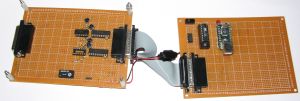
This was really neat. 8 bits XY and just TTL blanking. I had been doing some experiments to try to get a steady output from it and had rigged up a microcontroller (an 89C4051 from Atmel) to an interrupt pin on the Parallel Port. This let me trigger an interrupt at a preset rate ... I chose 12,000 times per second. I was not able to achieve this rate on the PC software side however this gave rise to an idea. I had been working with a USB to Serial converter at work and also had a USB to Parallel converter that I had not found a use for yet. The thought that I had was to use the same micro to regulate the data flowing from the USB converter to the LPT DAC at the 12 kHz rate I was using. Why not? So I did it. The result was a 12kpps USB DAC. I wrote some elementary software to play ILDA files and posted the project on my website at the time.
Here is a reproduction of the old page on the USB LPT DAC?.
So some years went by and I gained some experience with micro-controllers in general. In specific I learned how to use and program Atmel AVR's. These were much easier to use than the 8051 variants that I was used to using.
So some more time went by and I eventually met Norm Defayette of CoreTechs R&D. He had some really great kits for LPT DACs and some open source software (at the time) called Norm's Laser Show. But this was not what he was netfamous for. He had duplicated quite successfully ELM Chan's galvos and had made a kit for them. This was great as they were 18kpps galvos and there was nothing else in the price range at the time. I had approached him about possible doing an add on board for his LPT DACs to support the growing number of computers without LPT (Parallel Ports). This eventually turned into the Frame Streamer Express V1 (FSX1).
The FSX1 was essentially an updated LPT DAC (TTL RGB + Differential Outputs) with a USB converter and AVR micro. An ATMega8 to be exact. This was really cool.
Then we did an updated version that added 8 bit RGB color and faster output rates using an ATMega644.
My original goal had been to produce an Open Source USB DAC and since these were kits and commercially sold I did not quite reach my goal. I really wanted to give back to the community that provided so much valuable information. I wanted to give something that would be on the level of the LPT DAC.
The good news is that some really smart people in Italy made a new and very popular micro-controller development board called the Arduino. It was catching on fast!
It thought that this would be the way to go for providing a base to build a DAC upon. The development boards were getting cheaper and more capable fast. Soon they went from a Serial port to a FTDI USB to serial converter. This was the key. The only thing to overcome was the serial nature. The USB to parallel converter had flow control built into its data transfers through the use of Read and Write control lines. The serial versions did have flow control ... but would it work? The short answer was yes.
I spent some time exploring what features a USB DAC would need. I got a lot of information. Most laserists want everything and the kitchen sink. If you want to spend $1000 on a DAC then put in the kitchen sink. This DAC is the for the rest of us. So I settled on the minimum specs of: 12 bits XY Differential Output, more than TTL RGB and at least 30kpps max output rate. Remember this DAC is supposed to be the starter DAC.
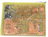
So before and during SELEM2010 I concocted the first Open Laser Show DAC. I had intended to populate the board I made (using Eagle CAD) and etched (using the Toner Transfer Method) however it was my first board and it turned out not so great.
I ended up having to really butcher the board to get it to work at all. Since I just used parts I had laying around it was not the "end product" any ways so that is the way prototyping goes.
I tried some new (old) concepts here. I tried a 2-bit R2R DAC made of resistors and I tried PWM ... both for RGB color output. Both worked OK. I found that the PWM worked well but I needed a killer filter to filter out the PWM noise. I am not too knowledgeable in that arena so I went with the R2R DAC... 2 bits was not enough so I tried 4 bits however I ran out of I/O. So 3 bits of R2R DAC for each color should work for the next version. I also needed some updated parts and I wanted to keep the cost under $20 and all easily found at Digikey.
So V3 was born.
It worked really well. It features 12 bits of XY and 3 bits of RGB. Plus I added a button on suggestion from Adam Burns and Andrew Kibler that it was a good idea to include a test frame feature. Since this was just a prototype I found a few things that I wanted to change and so was born OLSD V3B.
I brought V3B to SELEM2011 and found that there was some interest. I even managed to sell a few of them that I put together by trading my sleep for assembly time. I wanted to present a fully finsihed and complete concept. This paid off as I won an award. This was a really huge surprise as I expected to get the "Crappiest Projector" award for my woodwork projectors. Turns out I got the "Coolest Gadget" award instead. Really cool. Thanks everyone at SELEM2011 for that. Plus we all got the super nice shirts to boot.
Upon discussion with Andrew and some others I arrived at the conclusion that the OLSD needed some more colors. At least 4 bits. So I chewed on that a while as I had run out of IO for V3. I finally decided to add some 595 shift registers to add 16 bits more IO. This resulted in the ability to add 5 bits of RGB color. That gives a big 32767 colors + black. The problem with 5 bits of color with R2R DACs is that you need alot of resistors to make them. So upon suggestions from Andrew and some of my own thoughts I used resistor nets.
The first 4A board I etched myself was a FAILURE. The resistor nets are too small for my etching skills (or at least the vias are).
Try again...
I also forgot to mention I purchased the prototype PCB's from a great company up North in Canada called APCircuits. They do great work and deliver super fast (at a great price)!
Now the problem with resistor nets is that they are small and hard to wire in the R2R configuration because ... well I will let you figure that out. So in short I messed up. 4A worked but wasn't right... mostly because of a tricked I tried to do to make programming easier. Didn't work and it backfired. So was born 4B.
And here we are today....
More to come as time goes on.


